Blog
What Is a Battery Management System PCB BMS PCB?
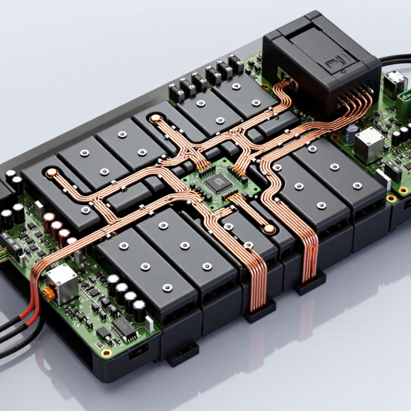
A Battery Management System PCB (BMS PCB) is the control center behind a safe, reliable battery pack. It monitors voltage, current, temperature, and charging conditions through carefully arranged sensing circuits. In an electric bicycle, for example, tiny measurement lines track each cell while copper paths carry substantial current to the motor. The board must remain accurate when the pack is cold, heavily loaded, or nearly full.
Battery expert Gregory L. Plett describes the BMS as “the brain of the battery.” This comparison is useful, but incomplete. A BMS PCB does more than make decisions. It measures physical conditions, balances cells, controls protection switches, and communicates with chargers or vehicle controllers. Its firmware also interprets changing battery behavior. That requires engineering judgment, not only attractive circuit layout.
Small errors matter. A poorly routed trace can introduce measurement noise. An undersized connector may heat during fast charging. Weak thermal design can hide dangerous temperature rises. No design is perfect. Real products require testing across aging, vibration, moisture, and repeated charge cycles. Engineers often refine protection thresholds after laboratory results reveal unexpected behavior.
This guide explains what a Battery Management System PCB (BMS PCB) contains, how its main circuits work, and why layout affects battery safety. It also examines cell balancing, state estimation, communication interfaces, and manufacturing considerations. The goal is practical understanding. Readers should see the PCB not as a simple switchboard, but as a carefully verified layer between stored energy and everyday equipment.
What Is a Battery Management System PCB?
A Battery Management System PCB is the control circuit inside a rechargeable battery pack. It monitors cell voltage, current, temperature, and charging status. The board helps keep each cell within a safe operating range. It may disconnect the pack when conditions become unsafe. Protection matters.
A typical BMS PCB includes a control chip, voltage sensing lines, temperature sensors, switching components, and a current measurement path. During charging, it can limit excessive current and detect abnormal voltage. During use, it can stop discharge before cells become dangerously depleted. Some designs also balance cell voltages, so one cell does not reach its limit too early. A small temperature sensor may sit close to the cells, where heat changes quickly.
In practical testing, wiring quality can matter as much as the circuit design. Loose sensor connections may create false readings. Poor heat removal can also reduce switching reliability. A board may work correctly on a bench but behave differently inside a crowded enclosure. This is an easy detail to underestimate. Designers should verify cutoff points, balancing performance, insulation distances, and communication signals under real load conditions. No BMS PCB can repair damaged cells or replace proper battery assembly. Its accuracy depends on calibration, component quality, and careful installation.
Core Functions of a BMS PCB
What Is a Battery Management System PCB (BMS PCB)?
Core Functions of a BMS PCB
A BMS PCB is the control board inside a rechargeable battery pack. It monitors each cell and manages safe electrical operation. Small sensing circuits measure cell voltage, pack current, and temperature. These readings help the controller identify abnormal conditions before damage occurs.
Protection is a central function. The board can disconnect charging during overvoltage or high-temperature events. It can also stop discharge when cells reach unsafe voltage levels. Short-circuit and overcurrent protection reduce risks caused by wiring faults or sudden load changes. Fast response matters here. A delayed cutoff can create excessive heat.
The PCB may balance cells by removing small amounts of energy from higher-voltage cells. This process helps maintain consistent capacity across the pack. It also estimates state of charge and state of health. These values support better charging decisions and service planning. Communication circuits can share battery data with an external controller or display.
In practical testing, sensor accuracy depends on layout, calibration, and stable connections. A calculated charge percentage can drift over time. That is easy to overlook. Designers should review measurement errors, thermal paths, and fault records under real load conditions. No protection circuit is perfect. Careful testing remains essential.
Key Components and Circuit Architecture
What Is a Battery Management System PCB BMS PCB?
A Battery Management System PCB is the control board that supervises rechargeable cells as a working pack. Its circuit architecture begins with cell-voltage sensing lines connected to an analog front end. This section measures each cell, often within millivolt-level limits. Small resistors and capacitors filter noise before measurements reach the microcontroller.
The microcontroller interprets voltage, temperature, current, and operating history. Temperature sensors sit near cells, power switches, and charging paths. A current shunt produces a tiny voltage that the monitoring circuit converts into charging or discharging data. Protection MOSFETs can disconnect the pack during overvoltage, deep discharge, excessive current, or short-circuit conditions. A balancing circuit uses controlled resistors to remove small amounts of energy from stronger cells. It is simple, but it creates heat.
Physical layout matters greatly. High-current copper paths should remain short and wide, while sensitive measurement traces need distance from switching nodes. A practical inspection should check creepage, connector polarity, fuse placement, and thermal airflow. Communication lines may provide status data to external equipment, but isolation requirements depend on the pack design and working voltage.
The circuit may pass a basic test yet fail under vibration or cold temperatures. That weakness deserves attention. Cell tolerances, sensor placement, and firmware thresholds can also produce different results in real operation. Engineers often validate the PCB with controlled fault tests, thermal checks, repeated charge cycles, and carefully recorded voltage readings. Small layout errors can become expensive failures.
What Is a Battery Management System PCB (BMS PCB)? Key Components and Circuit Architecture
| Circuit Block | Primary Function | Typical Components | Typical Electrical Range | Protection or Control Role | Key Design Considerations |
|---|---|---|---|---|---|
| Cell Voltage Monitoring | Measures the voltage of individual cells or parallel cell groups. | Multichannel battery monitor, precision resistor networks, input filters, balancing switches. | Approximately 2 to 5 V per lithium-ion cell; commonly 4 to 16 monitored series cells per circuit section. | Detects overvoltage, undervoltage, cell imbalance, and abnormal voltage changes. | Use matched components, short sensing paths, suitable input filtering, and adequate creepage distance. |
| Cell Temperature Sensing | Monitors cell, busbar, MOSFET, and PCB temperatures. | NTC thermistors, resistor dividers, analog-to-digital converter inputs, thermal interfaces. | Common measurement range: approximately -40°C to 125°C, depending on the sensor and system. | Stops or limits charging and discharging during overtemperature or undertemperature conditions. | Place sensors near heat sources and representative cells; define sensor-fault detection thresholds. |
| Battery Fuel-Gauge Measurement | Calculates pack current, charge level, energy flow, and battery condition. | Current-sense resistor, differential amplifier or monitor, ADC, coulomb-counting logic. | Current capability may range from a few amperes to several hundred amperes, depending on the pack. | Supports state-of-charge, state-of-health, remaining-capacity, and power-limit calculations. | Current-sense accuracy, offset drift, Kelvin routing, and calibration strongly affect measurement quality. |
| Current-Sensing Network | Measures charge and discharge current in real time. | Low-resistance shunt, isolated current sensor, differential input filter, protection resistors. | Typical shunt values are approximately 0.1 mΩ to 5 mΩ for high-current battery packs. | Identifies overcurrent, short-circuit events, charge termination, and abnormal load conditions. | Consider power dissipation, pulse current, thermal rise, common-mode voltage, and measurement bandwidth. |
| Passive Cell Balancing | Reduces voltage differences by dissipating energy from higher-voltage cells. | Bleed resistors, balancing MOSFETs, control outputs, thermal monitoring. | Typical balancing currents range from approximately 30 mA to 200 mA. | Improves usable pack capacity and reduces cell overvoltage risk during charging. | Balance resistor power, PCB heat spreading, activation time, and cell-voltage thresholds must be evaluated. |
| Active Cell Balancing | Transfers energy from higher-voltage cells to lower-voltage cells or the pack bus. | Inductors or capacitors, switching transistors, bidirectional converters, control circuitry. | Balancing current can range from hundreds of milliamperes to several amperes. | Provides faster balancing with lower energy loss than resistor-based balancing. | Requires more components, careful electromagnetic compatibility design, and robust switching control. |
| Charge and Discharge Switching | Connects or disconnects the battery from the charger and load. | Back-to-back N-channel MOSFETs, gate drivers, charge-pump circuits, pull-down resistors. | Voltage and current ratings must exceed the maximum pack voltage and expected load current. | Provides electronic protection against overcharge, overdischarge, overcurrent, and short circuit. | Account for MOSFET resistance, gate-source limits, switching transients, heat dissipation, and fault recovery. |
| Precharge Circuit | Limits inrush current when connecting a battery to a capacitive load. | Precharge resistor, auxiliary MOSFET or relay, voltage feedback, timing control. | Precharge resistance is selected from load capacitance, allowable inrush current, and precharge time. | Reduces contact welding, connector arcing, and stress on input capacitors. | Resistor pulse-energy rating and failure detection are important for reliable operation. |
| Fuse and Hardware Safety Path | Provides fail-safe protection when electronic switching cannot interrupt a severe fault. | Pack fuse, fusible link, thermal fuse, pyro-fuse interface, redundant cutoff path. | Fuse ratings are selected according to continuous current, interrupt rating, and fault-current level. | Protects against catastrophic short circuits and selected single-point failures. | Coordinate fuse behavior with MOSFET protection, conductor ratings, and enclosure safety requirements. |
| Microcontroller and Firmware | Processes measurements and manages protection, balancing, diagnostics, and operating states. | Microcontroller, watchdog, nonvolatile memory, clock source, reset circuit. | Common supply domains include approximately 3.3 V or 5 V logic, depending on the architecture. | Executes threshold checks, fault logging, state-of-charge estimation, and controlled shutdown. | Use watchdog supervision, validated fault states, secure parameter storage, and independent safety checks. |
| Power Regulation | Generates stable low-voltage rails for sensing, logic, communication, and gate control. | DC-DC converter, linear regulator, filter capacitors, transient protection devices. | Converts the battery voltage to logic rails such as 3.3 V, 5 V, or an isolated intermediate voltage. | Maintains circuit operation across battery voltage variation and transient events. | Evaluate quiescent current, thermal performance, switching noise, reverse polarity, and load-dump tolerance. |
| Isolation and Level Shifting | Separates high-voltage battery domains from low-voltage control or communication domains. | Digital isolator, optocoupler, isolated DC-DC converter, level-shifting interface. | Isolation voltage is application-specific and may be several hundred volts in high-voltage battery systems. | Limits hazardous voltage transfer and improves system-level fault containment. | Maintain creepage, clearance, insulation rating, common-mode transient immunity, and isolation barriers. |
| Communication Interface | Exchanges battery data and fault information with a charger, vehicle controller, or host system. | CAN transceiver, UART interface, RS-485 transceiver, wireless interface, termination network. | Communication voltage and data rate depend on the selected protocol and system architecture. | Reports voltage, current, temperature, state of charge, alarms, and available power limits. | Provide electromagnetic protection, bus termination where required, isolation when necessary, and defined fail-safe behavior. |
| Surge and ESD Protection | Protects sensitive BMS electronics from electrostatic discharge and electrical transients. | TVS diodes, common-mode chokes, ferrite beads, RC filters, surge-limiting components. | Protection levels are selected according to the battery bus, connector environment, and applicable test requirements. | Reduces damage from connector events, inductive switching, cable transients, and electrostatic discharge. | Place protection devices close to entry points and keep high-energy transient paths short and wide. |
| Connector and Sense Wiring | Connects cell taps, pack terminals, temperature sensors, power paths, and communication lines. | Cell-tap connector, terminal blocks, busbars, harnesses, keyed signal connectors. | Signal wiring carries low current; power terminals are sized for the pack's continuous and peak current. | Ensures correct polarity, reliable measurement, and secure power delivery. | Use keyed connectors, locking features, separation of power and signal paths, and clear service labeling. |
| PCB Layout and Thermal Management | Provides the physical architecture for safe signal integrity, current flow, and heat removal. | Multi-layer PCB, copper pours, thermal vias, controlled grounding, isolation slots, heat spreaders. | Trace width and copper thickness are selected from current, temperature rise, and allowable voltage drop. | Reduces measurement errors, hot spots, electromagnetic interference, and insulation risk. | Separate high-current, high-voltage, and sensitive analog areas; use Kelvin connections for precision sensing. |
Note: Electrical ranges are representative engineering values. Final ratings and thresholds must be selected according to cell chemistry, series count, pack voltage, load profile, environmental conditions, and applicable safety requirements.
How a BMS PCB Monitors and Protects Batteries
What Is a Battery Management System PCB BMS PCB?
How a BMS PCB Monitors and Protects Batteries
A Battery Management System PCB acts as the battery pack’s control center. It measures each cell’s voltage, pack current, and temperature through dedicated sensors. These readings help the circuit detect abnormal conditions before they damage the cells. In a well-designed pack, measurement accuracy matters because a small voltage error can affect charging decisions.
The BMS PCB controls charging and discharging through electronic switches, often using power MOSFETs. If a cell reaches an unsafe voltage, it can stop charging. If the pack current rises sharply, it can disconnect the load. Temperature limits add another layer of protection. A sensor near the hottest cell may trigger a shutdown when heat increases unexpectedly. It can also balance cells by reducing energy from stronger cells during charging.
Cell balancing is not magic.
The PCB may calculate remaining capacity from voltage, current, and previous usage. However, state-of-charge estimates can drift as batteries age or operate in cold conditions. That limitation deserves attention. A protection circuit can respond quickly, but it cannot repair damaged cells or compensate for poor wiring. Engineers should verify sensor placement, connector quality, fuse selection, and cutoff thresholds during testing. A controlled test with a calibrated meter often reveals errors that software alone misses. Reliable protection depends on the PCB, the battery cells, and the complete pack design working together.
Applications and Selection Considerations for BMS PCBs
What Is a Battery Management System PCB BMS PCB?
A BMS PCB is the control board inside a rechargeable battery pack. It measures cell voltage, pack current, temperature, and charging conditions. The circuit protects cells from overcharging, deep discharge, overheating, and excessive current. It can also balance cells, improving usable capacity and pack stability. Small packs may use a compact board, while industrial systems need stronger sensing and communication circuits.
Applications and Selection Considerations for BMS PCBs
BMS PCBs support electric tools, energy storage units, medical equipment, mobility devices, and backup power systems. Selection should begin with battery chemistry, cell count, maximum current, balancing method, and operating temperature. A board for a low-current device may fail in a motor-driven application. That mistake is more common than expected. Check connector layout, enclosure space, vibration exposure, and communication needs before ordering samples. CAN, UART, or other interfaces may simplify system monitoring, but compatibility must be tested with the host controller. Reliable designs also include short-circuit protection, measured thermal limits, and clear fault reporting. Verify applicable safety requirements early. A qualified engineer should review the final design and test it under realistic charging, discharging, and fault conditions.
Tips: Compare the PCB rating with real peak current, not only the average load. Test sensors near heat sources, because temperature readings can become misleading. Inspect balancing performance across several charge cycles. Keep written test records. They reveal weak assumptions. A rushed selection can look acceptable on a bench, yet behave differently inside a sealed enclosure.
What Is a Battery Management System PCB (BMS PCB)?
A BMS PCB monitors cell voltage, pack current, and temperature while providing protection against overcharge, over-discharge, overcurrent, and abnormal thermal conditions. The chart shows representative lithium-ion cell-series configurations commonly used in different applications.
Representative configurations: actual pack voltage and cell count vary according to system power, runtime, safety requirements, and application design. Higher series counts generally require more voltage-monitoring channels, stronger isolation, and more advanced balancing and protection functions.