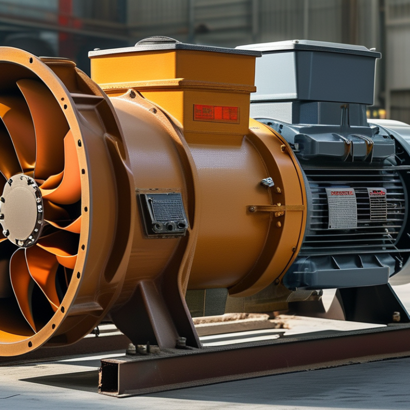
| Basic Definition | Equipment Type | Radial-flow centrifugal fan | Uses a rotating impeller to draw air or flue gas axially and discharge it radially at increased pressure. | Unlike an axial fan, the centrifugal design is well suited to systems requiring relatively high pressure against ducts, burners, heat-transfer surfaces, and dust-collection equipment. |
| Primary Boiler Applications | Forced-draft, induced-draft, primary-air, secondary-air, and flue-gas recirculation service | Supplies combustion air, removes combustion gases, or recirculates controlled flue gas. | The fan arrangement must match the required gas temperature, pressure, dust loading, and corrosion conditions. |
| Energy Conversion | Mechanical shaft power converted into gas velocity and static pressure | The motor rotates the impeller; the impeller transfers energy to the gas; the casing converts part of the velocity into useful pressure. | Actual performance depends on speed, impeller geometry, gas density, system resistance, and operating point. |
| Typical Installation | Mounted between ductwork and a boiler air or flue-gas circuit | Connected to inlet and outlet ducts, dampers, expansion joints, silencers, filters, or a stack system. | Proper alignment and sealing reduce vibration, leakage, noise, and unnecessary energy consumption. |
| Key Internal Components | Impeller | Rotor with a back plate, front plate or shroud, and multiple curved or radial blades | Accelerates and redirects the gas from the impeller eye toward the outer circumference. | Blade shape, diameter, width, and outlet angle determine airflow, pressure, efficiency, and noise. |
| Blades | Forward-curved, backward-curved, or radial-blade profile | Transfers momentum to the gas and establishes the fan's pressure-flow characteristics. | Backward-curved blades generally provide stable operation and high efficiency; radial blades are more tolerant of particulate-laden gas. |
| Inlet Eye and Inlet Cone | Central impeller opening with a shaped inlet passage | Guides gas smoothly into the impeller with minimal turbulence. | Uneven or swirling inlet flow can reduce capacity, increase noise, and create uneven blade loading. |
| Volute Casing | Spiral-shaped housing surrounding the impeller | Collects high-velocity gas leaving the impeller and converts part of its velocity into static pressure. | Clearance between the impeller and casing must be controlled to limit recirculation and efficiency loss. |
| Shaft | Steel rotating shaft supported by bearings | Transmits torque from the drive to the impeller. | It must withstand torsional load, bending load, thermal expansion, and the fan's maximum operating speed. |
| Bearings | Rolling-element or sleeve bearings, commonly positioned outside the gas path | Support the shaft and maintain the impeller's designed running position. | Lubrication, temperature, alignment, and vibration monitoring are essential for reliable service. |
| Fan Housing and Frame | Welded or fabricated casing mounted on a rigid base | Contains the rotating assembly and provides structural support for duct and drive connections. | The frame must resist vibration and thermal distortion without transmitting excessive forces to connected ductwork. |
| How It Works | 1. Gas Entry | Gas enters through the inlet cone into the center of the impeller. | Creates a controlled and relatively uniform flow into the rotating wheel. | Inlet obstructions, elbows, or dampers positioned too close to the fan can disturb the flow profile. |
| 2. Impeller Rotation | The motor rotates the impeller around its shaft. | Rotational motion transfers kinetic energy and momentum to the gas. | Fan speed strongly affects airflow and pressure; operation must remain within the manufacturer's safe speed limit. |
| 3. Radial Acceleration | Gas moves from the impeller eye outward toward the blade tips. | Centrifugal action raises gas velocity and produces a pressure increase. | High temperature or low-density gas requires a different volumetric flow and power calculation than cool air. |
| 4. Pressure Recovery | The volute or diffuser slows part of the gas flow. | Some velocity pressure is converted into static pressure for overcoming system resistance. | A correctly sized casing improves efficiency and reduces turbulence and noise. |
| 5. Gas Discharge | Pressurized gas exits through the outlet flange into the boiler duct system. | Delivers combustion air or transports flue gas to the next process stage. | Outlet duct design should limit abrupt changes, excessive bends, leakage, and unbalanced pressure distribution. |
| 6. System Control | Flow is adjusted by variable-speed drive, inlet guide vanes, or dampers. | Matches fan output with boiler load and combustion-control requirements. | Variable-speed control is often more energy-efficient than throttling with a damper, especially during part-load operation. |
| Typical Operating Data | Airflow Capacity | Approximately 1,000 to 500,000 m³/h, depending on fan size and boiler duty | Defines the volume of air or gas moved per unit of time. | Actual selection must account for gas temperature, elevation, moisture, dust, leakage, and required excess air. |
| Pressure Rise | Approximately 500 to 10,000 Pa for many industrial boiler fan applications | Provides the force required to overcome burner, boiler-pass, duct, filter, and stack resistance. | Forced-draft and induced-draft duties may require different pressure margins and control strategies. |
| Typical Rotational Speed | Approximately 700 to 3,000 rpm, depending on impeller diameter and design | Determines the fan's pressure and flow capability. | Higher speed can reduce physical size but may increase noise, wear, vibration, and power demand. |
| Gas Temperature | Ambient air service may be near room temperature; induced-draft service can commonly range from 80°C to 250°C | Determines material selection, bearing arrangement, shaft design, and thermal expansion requirements. | Temperature limits vary by construction; high-temperature flue-gas fans require suitable cooling and expansion provisions. |
| Drive Arrangement | Direct-coupled or belt-driven motor; larger units commonly use coupling or specialized drive systems | Supplies rotational power to the fan shaft. | Drive selection affects efficiency, maintenance requirements, speed flexibility, and allowable operating temperature. |
| Motor Power | Typically from a few kilowatts to several hundred kilowatts for industrial boiler systems | Provides the power required to overcome gas-system resistance at the design flow. | Motor sizing should include fan efficiency, gas density, transmission losses, and a reasonable service margin. |
| Efficiency Range | Approximately 60% to 85% for many properly selected centrifugal fans | Indicates how effectively input shaft power is converted into useful gas power. | Efficiency changes with operating point; operating close to the fan's best-efficiency region reduces energy use. |
| Performance Relationships | Fan Affinity Law: Flow | At constant gas density, Q₂/Q₁ ≈ N₂/N₁ | Airflow changes approximately in proportion to rotational speed. | Real systems may deviate because duct resistance, dampers, and gas conditions also change. |
| Fan Affinity Law: Pressure | At constant gas density, ΔP₂/ΔP₁ ≈ (N₂/N₁)² | Pressure capability changes approximately with the square of speed. | Small speed increases can produce substantial pressure and power increases. |
| Fan Affinity Law: Power | At constant gas density, P₂/P₁ ≈ (N₂/N₁)³ | Power demand rises approximately with the cube of rotational speed. | Speed control must be coordinated with motor capacity and overload protection. |
| Gas Density Effect | Pressure and power are influenced by absolute temperature, pressure, and gas composition | Hot flue gas is less dense than cold air at the same absolute pressure. | Fan selection should use the actual operating gas condition rather than standard air values alone. |
| Operating Point | Intersection of the fan performance curve and the system resistance curve | Defines the actual airflow and pressure produced during operation. | Operation far from the preferred range can cause instability, excessive vibration, noise, or inefficient power use. |
| Reliability and Maintenance | Impeller Balance | Dynamic balancing is required after manufacture and may be needed after repairs or buildup removal. | Prevents excessive centrifugal forces during rotation. | Dust accumulation, erosion, corrosion, or a missing balance weight can create severe vibration. |
| Clearances | Controlled gaps between the impeller, inlet cone, and casing | Limit internal leakage and prevent mechanical contact. | Clearances should be inspected after thermal cycling, bearing wear, or impeller replacement. |
| Vibration Monitoring | Routine measurement at bearing housings and structural points | Helps identify imbalance, misalignment, looseness, bearing defects, or resonance. | Trend data is more useful than a single reading because gradual changes can indicate developing faults. |
| Dust and Deposit Control | Inspection and cleaning of blades, inlet passages, and casing | Maintains aerodynamic balance and available flow area. | Deposits can reduce capacity, lower efficiency, and cause dangerous rotor imbalance. |
| Safety Protection | Guards, access interlocks, emergency stop, overload protection, and appropriate temperature monitoring | Protects personnel and equipment from rotating parts, overheating, and abnormal operation. | The fan should be isolated and locked out before inspection or maintenance. |
| Advantages and Limitations | Main Advantages | High pressure capability Flexible control Robust construction | Suitable for complex boiler air and flue-gas systems with significant resistance. | Correct selection is essential because oversized fans can waste energy and undersized fans can limit boiler output. |
| Common Limitations | Noise, vibration, wear, corrosion, and sensitivity to poor inlet flow | These factors can reduce efficiency and shorten service life. | Material selection, acoustic treatment, proper duct layout, and preventive maintenance reduce these risks. |
| Forced-Draft Fan | Installed upstream of the furnace and operates on relatively clean combustion air. | Pushes air into the burner or furnace to support combustion. | Usually experiences lower dust loading but must provide stable air pressure over the boiler load range. |
| Induced-Draft Fan | Installed downstream of the boiler and often exposed to hot flue gas. | Pulls combustion gas through the boiler and maintains the required furnace draft. | Must account for high temperature, moisture, corrosive constituents, and possible particulate loading. |