How to Choose a Three Phase Transformer in 2026?
Choosing a Three Phase Transformer in 2026 means balancing load, efficiency, reliability, and future expansion. The decision is not just about matching a nameplate rating. A unit must also suit its voltage levels, installation environment, cooling method, impedance, and expected harmonics. A transformer that looks right on a spreadsheet can still disappoint when motors start, ambient temperatures climb, or the site adds equipment.
The International Energy Agency’s 2023 report, Electricity Grids and Secure Energy Transitions, says annual grid investment must rise to more than $600 billion by 2030. That wider grid challenge makes careful equipment selection more important, not less. IEA Executive Director Fatih Birol described the shift in its 2024 outlook: “The world is entering the Age of Electricity.” It is a broad observation, but it has practical meaning for facilities choosing transformers.
Start with measured demand, not guesswork. Check peak and average load, future growth, harmonic-producing equipment, and the consequences of an outage. Then compare losses across the transformer’s expected operating hours; a lower purchase price may cost more over time. Confirm the site’s ambient temperature, altitude, ventilation, and available space. Small details matter. A hot, dusty plant room is not the same as a clean indoor substation.
This guide lays out the key checks for choosing a Three Phase Transformer in 2026. It also flags where rules of thumb can fail. No checklist replaces a qualified electrical engineer’s review of the actual load and site conditions. That caveat is easy to overlook—and worth keeping.
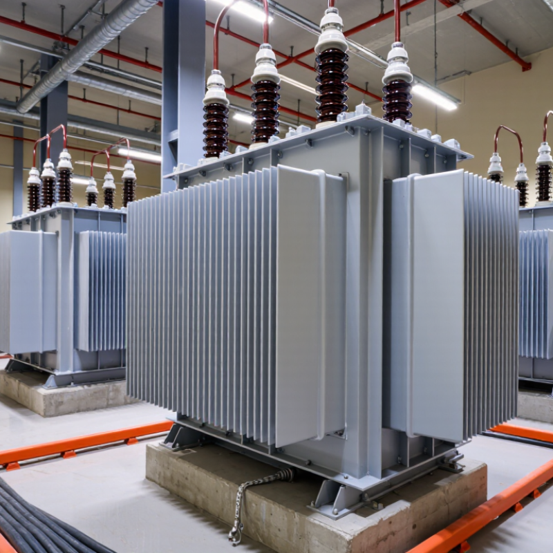
Define Load and Growth Margin: Select kVA for Peak Demand
For a three-phase transformer, size from the highest credible coincident load, not the sum of every nameplate rating. Use interval-meter data where possible; a brief motor-starting surge and a sustained evening peak are different design problems. Convert peak current to apparent power with kVA = √3 × line voltage × line current ÷ 1,000. Then check power factor, nonlinear loads, ambient temperature, and starting current. EPRI’s 2024 data-center analysis estimated that U.S. data centers used about 4.4% of electricity in 2023, with their share potentially reaching 4.6–9.1% by 2030. That forecast is not a sizing rule, but it shows why load growth deserves a real estimate.
Add a growth margin based on planned equipment, operating hours, and the time until the next upgrade—not a convenient round number. A 15–25% allowance may suit a stable site, but fast-growing facilities can outgrow it quickly. Check the selected kVA against the transformer’s cooling and overload limits, and consider harmonics from drives or power electronics. A spreadsheet forecast can look precise while missing a new production line; revisit it with actual operating data.
Tips: Record peak demand at 15-minute intervals, including seasonal extremes. List known additions separately, then model their coincidence with existing loads. Leave room for growth, but avoid oversizing without checking efficiency and cost.
Match Primary/Secondary Voltage and Vector Group (e.g., 480Y/277 V)
When choosing a three-phase transformer, compare its primary voltage with the voltage measured at the supply, not just the value on an old drawing. Check the secondary against the equipment nameplates and expected loads. A 480Y/277 V secondary provides 480 V between phases and 277 V from phase to neutral. That distinction matters when a site has both three-phase motors and 277 V lighting. Small mismatch, big trouble.
The vector group describes winding connections and phase displacement. For example, a delta primary and grounded-wye secondary may suit a system needing a neutral, but the exact group must match the installation design. Confirm the clock number and phase rotation before connecting equipment or paralleling transformers. Also check grounding, neutral loading, and the source’s available voltage. A neat-looking specification can still hide a mismatch. Even experienced teams can overlook a legacy load or an unusual connection; I would verify the actual wiring and nameplate details before ordering. If the project documents disagree, pause and have a qualified engineer resolve the discrepancy.
Verify Frequency, Cooling, and IEC 60076 Nameplate Ratings
How to Choose a Three Phase Transformer in 2026?
Verify Frequency, Cooling, and IEC 60076 Nameplate Ratings
Frequency is not a minor checkbox. A 50 Hz transformer connected to a 60 Hz system may experience higher magnetic flux and excess heating if voltage stays unchanged. Confirm the supply frequency, voltage, and operating range together. The IEA’s Electricity Grids and Secure Energy Transitions report (2023) says over 80 million kilometres of grids must be added or replaced by 2040. That is grid-scale context, not a transformer demand forecast.
Match cooling to the installation. A sealed indoor room, dusty workshop, and outdoor pad have different heat and ventilation conditions. Check the nameplate’s cooling class, rated power, voltage ratio, vector group, impedance, tap range, and temperature rise against the load and site conditions. The IEC 60076 series covers power-transformer requirements, including temperature-rise tests. Do not rely on kVA alone. I would also verify altitude and ambient temperature with the supplier; these details are easy to overlook.
Tips: Photograph the full nameplate before ordering. Compare every rating with the one-line diagram and utility requirements. Check the plate. If the cooling or insulation marking is unclear, ask for the applicable IEC 60076 documentation before approval.
How to Choose a Three-Phase Transformer in 2026
Verify the supply frequency, cooling designation, and IEC 60076 nameplate ratings before selecting a transformer.
The chart compares idealized, normalized sine waves at 50 Hz and 60 Hz over 100 ms. Match the transformer’s nameplate frequency to the supply; do not assume a 50 Hz unit is suitable for 60 Hz service, or vice versa, without manufacturer confirmation. Also check rated power, primary and secondary voltages, vector group, impedance, and cooling designation against the installation requirements and applicable IEC 60076 specifications.
Assess Impedance and Fault Duty: Distribution Units Often Use 4–6% Z
When choosing a three-phase transformer, assess impedance alongside kVA and voltage ratings. Distribution units often have 4–6% impedance, but that range is a starting point, not a specification. It matters.
At a given voltage, lower impedance generally allows more fault current to flow through the transformer. A rough estimate divides rated current by per-unit impedance; for example, 5% impedance is 0.05 per unit. Actual available fault current also depends on the upstream supply and cable impedance. That number affects breaker interrupting ratings and protective-device coordination. Check the nameplate.
Higher impedance can limit fault current, yet it may cause greater voltage drop under load. Consider motor starting, long feeder runs, and changing demand. If transformers will operate in parallel, compare their impedance values and ratios; mismatches can cause uneven load sharing. I would not select a unit from the percentage alone. Confirm the site fault study, expected loading, and equipment ratings with a qualified electrical engineer. Real installations can differ from neat calculations, especially when older cables or incomplete utility data are involved. A little uncertainty deserves a closer check.
How to read the estimates: Full-load current is calculated as kVA × 1,000 ÷ (√3 × 480 V). The fault-current range is an approximate symmetrical RMS value at the transformer secondary terminals, calculated using 4–6% impedance and assuming an infinitely strong primary source. Actual fault current is generally affected by source and conductor impedance, transformer design, and system configuration. The 4–6% range is illustrative; use the selected unit’s nameplate impedance and applicable electrical codes for final design.
Compare Efficiency with DOE 10 CFR Part 431 Standards for 2026 Deployment
How to Choose a Three Phase Transformer in 2026?
For a 2026 project, compare each candidate with the DOE efficiency requirements that apply to its transformer category and manufacture date under 10 CFR Part 431. Coverage depends on details such as distribution-transformer type, rated capacity, and voltage. Check the applicable table and test procedure; a three-phase label alone does not establish which requirement applies. Small details matter.
Compare efficiency figures measured on the same basis. DOE’s prescribed procedure uses defined test conditions, while actual site performance depends on load profile, temperature, and operating hours. Ask for documented efficiency data and loss figures, including no-load losses that continue even when demand is low. A number copied from a brochure may not tell the whole story. Check the scope.
Then estimate annual energy use using the facility’s expected load, not only the transformer’s nameplate rating. For example, a unit serving a lightly loaded building may make no-load losses especially relevant. Verify that the supplier’s compliance documentation matches the exact model and the rules applicable to its production date. Also confirm installation space, ventilation, and service access. I would still challenge any comparison that ranks units on efficiency alone; purchase cost, loading patterns, and maintenance needs can change the practical choice. Not just the label.
