Blog
How to Choose the Right Machine Spindle for Your Needs
Choosing the right Machine Spindle can determine whether a machining center delivers consistent parts or repeated problems. The decision involves more than speed and price. Material, tool diameter, cutting depth, duty cycle, cooling, and available power must work together.
Professor Yusuf Altintas, a leading authority in machining dynamics, describes the spindle as “the heart of the machine tool.” That comparison is practical. A spindle running at 24,000 rpm may suit aluminum aerospace components, while a slower, high-torque unit may perform better on hardened steel. The wrong match can create chatter, rough surfaces, overheated bearings, and shortened tool life.
Start with the workpiece.
Review the materials, tolerances, tooling system, and expected production hours. Check the spindle’s continuous power, peak torque, maximum speed, bearing arrangement, and runout specification. A catalog’s peak rating may look impressive, but continuous performance often matters more during long cutting cycles. Cooling design matters too. Air cooling may fit light-duty work, while oil-air or liquid cooling can support demanding production environments.
I have seen specifications treated as guarantees. They are not. Real results depend on tool balance, fixture rigidity, programming, and maintenance. This is where careful testing becomes valuable. Request cutting data, vibration limits, service records, and compatibility details before purchasing.
The best Machine Spindle is not always the fastest. It is the one that matches your process honestly, including its weaknesses. A short trial cut may reveal more than a polished brochure.
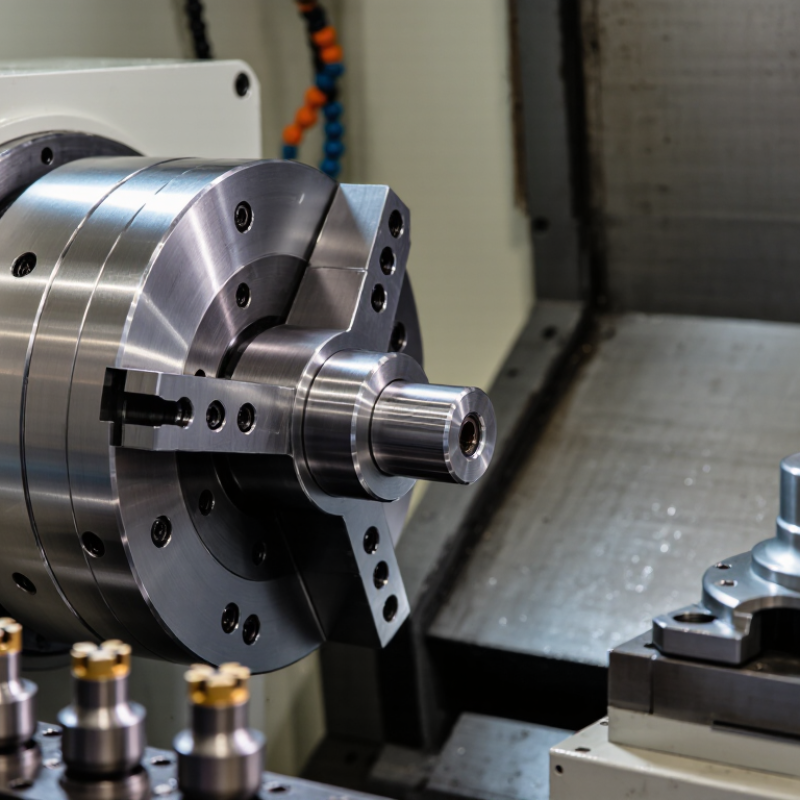
Define the Spindle’s Role in Your Machining Process
How to Choose the Right Machine Spindle for Your Needs
Define the Spindle’s Role in Your Machining Process
Before comparing specifications, define what the spindle must accomplish. Its job may involve rough material removal, fine finishing, drilling, or continuous production. Each task demands a different balance of speed, torque, rigidity, and thermal stability. A high-speed spindle is useful for small cutters and detailed surfaces. However, it may struggle when removing heavy material. A slower spindle with stronger torque can handle demanding cuts more reliably.
Study your actual machining conditions, not only the machine’s brochure. Consider material hardness, tool diameter, cutting depth, duty cycle, and required surface quality. I have seen operators choose maximum speed, then discover excessive vibration during deep cuts. That mistake wastes time and shortens tool life. Check the spindle’s power curve across its working range. Rated power alone can be misleading. Measure sound, temperature, and vibration during a realistic trial cut. Small details matter.
Match Spindle Speed and Torque to Material Requirements
Choosing the right machine spindle starts with the material, not the machine’s maximum speed. Aluminum often rewards high spindle speed and moderate torque. Steel usually needs lower speed and stronger torque. Wood and plastics can vary widely, especially when heat builds inside the cut.
A useful calculation begins with cutting speed, tool diameter, and material guidance. A small cutter may require faster rotation to maintain an effective cutting speed. However, speed alone cannot prevent chatter or tool deflection. During milling tests, I watch spindle load, surface finish, chip shape, and temperature. These details reveal problems earlier than sound alone.
Torque matters most when the tool engages heavily or removes tough material. A spindle with high speed but weak low-end torque may stall during deep steel cuts. That result can damage the tool and spoil the workpiece. It happened to me during an aggressive test cut. The selected speed looked correct, but the feed and depth were unrealistic. This was a useful reminder: published ratings are starting points, not guarantees.
Choose a spindle with a practical speed range and enough continuous torque. Peak torque figures can mislead. Check how performance changes across the operating range. Leave some capacity for tool wear, interrupted cuts, and imperfect setup. Material hardness also changes between batches, so one fixed setting rarely works forever. Test conservatively, record the results, and adjust one variable at a time.
| Workpiece Material | Typical Machining Applications | Recommended Spindle Speed Range (10 mm Carbide Cutter) | Typical Cutting Speed Range | Suggested Continuous Torque | Suggested Spindle Power | Selection Priority | Key Considerations |
|---|---|---|---|---|---|---|---|
| Aluminum Alloys | High-speed milling, pocketing, profiling, drilling | 12,000–24,000 rpm | 380–750 m/min | 1.5–4 N·m | 3–8 kW | High speed and efficient chip evacuation | Use a spindle with strong acceleration and adequate airflow or coolant to prevent chip recutting and built-up edge. |
| Brass and Copper Alloys | Fine milling, engraving, drilling, connector and fitting production | 10,000–22,000 rpm | 315–690 m/min | 1.5–4 N·m | 2–6 kW | High speed with smooth torque delivery | Sharp tools and stable runout control are important for surface finish and burr reduction. |
| Mild Steel | General milling, slotting, drilling, roughing | 4,000–10,000 rpm | 125–315 m/min | 8–20 N·m | 5–15 kW | Balanced speed, torque, and thermal stability | A spindle with constant-power capability and sufficient low-speed torque is preferred for heavier cuts. |
| Stainless Steel | Contouring, deep pocketing, drilling, semi-finishing | 2,500–7,000 rpm | 80–220 m/min | 12–30 N·m | 7–18 kW | High torque and controlled heat generation | Avoid prolonged dwelling and inadequate chip evacuation, which can promote work hardening and tool damage. |
| Tool Steel | Die and mold machining, roughing, finishing | 2,000–6,000 rpm | 60–190 m/min | 15–35 N·m | 10–22 kW | High rigidity and sustained torque | Select bearings, cooling, and tool holding for continuous high loads and interrupted cutting conditions. |
| Cast Iron | Face milling, drilling, boring, rough machining | 2,500–7,000 rpm | 80–220 m/min | 10–28 N·m | 7–18 kW | Torque capacity and vibration resistance | A rigid spindle and suitable filtration are valuable because abrasive cast-iron dust can affect machine components. |
| Titanium Alloys | Low-speed roughing, contouring, aerospace component machining | 1,500–5,000 rpm | 45–160 m/min | 15–40 N·m | 10–25 kW | High torque, rigidity, and thermal control | Use conservative cutting conditions, strong coolant delivery, and a spindle designed for continuous load at low speed. |
| Engineering Plastics | Routing, profiling, drilling, trimming, low-load milling | 10,000–24,000 rpm | 300–750 m/min | 0.8–3 N·m | 1.5–5 kW | High speed with low vibration and precise control | Prevent melting by using sharp tools, adequate chip clearance, and cutting conditions appropriate to the specific polymer. |
| Carbon Fiber Reinforced Polymer | Trimming, drilling, edge finishing, composite panel machining | 8,000–20,000 rpm | 250–630 m/min | 1–4 N·m | 2–7 kW | High speed, low runout, and dust management | Use suitable composite tooling and extraction; abrasive fibers can accelerate tool wear and contaminate the machine. |
| Selection note: The values are practical starting ranges for spindle selection, not universal cutting parameters. Actual requirements depend on tool diameter, flute count, material grade, depth and width of cut, feed rate, workholding, machine rigidity, and coolant strategy. Spindle torque can be estimated from power and speed using: Torque (N·m) = 9,549 × Power (kW) ÷ Speed (rpm). | |||||||
Select the Appropriate Spindle Taper and Tool Interface
How to Choose the Right Machine Spindle for Your Needs
Choosing a spindle begins with the taper and tool interface, not maximum speed. The taper transfers cutting forces into the spindle nose. A steep-taper interface, covered by ISO 7388-1, suits general milling and strong axial retention. HSK interfaces, standardized under ISO 12164, use dual contact for improved radial stability at high speed. That difference matters when machining thin walls, deep cavities, or hard alloys.
MarketsandMarkets reported that the global machine tools market was valued at about USD 95 billion in 2024. Its forecast also shows continued growth through 2029. More machines will combine high-speed cutting with automated tool changes. Therefore, inspect the complete interface system: taper size, flange contact, pull-stud design, coolant delivery, and toolholder balance. A large taper is not automatically better. It can add rotating mass and reduce acceleration.
Tips: Match the interface to real cutting loads. For heavy roughing, prioritize rigidity and drawbar force. For high-speed finishing, check balance grades and contact accuracy. Ask for test data at your target RPM. ISO 16084 recommends balancing principles for rotating tools, but shop conditions still influence results. Measure runout at the tool tip, not only at the holder. I have seen a technically correct taper perform poorly after careless cleaning. That detail is easy to underestimate. Review actual tool life, vibration, and changeover time before final selection.
Evaluate Cooling, Power, Accuracy, and Maintenance Features
Choosing a machine spindle starts with its working environment, not its advertised speed. Heat changes bearing clearance, tool length, and surface finish. A water-cooled spindle suits long cutting cycles, while air cooling may simplify maintenance in dusty workshops. The U.S. Department of Energy reports that motor-driven systems consume about 23% of American electricity, so power efficiency deserves attention. More power is not always better. Match continuous torque to the material, cutter diameter, and expected duty cycle. Short overload ratings can mislead.
Accuracy requires measurable evidence. Ask for positioning and repeatability results tested under relevant conditions, using ISO 230-2 methods. Check thermal drift after several hours, not only during a cold start. Small errors matter. A 0.01 mm shift can spoil tight-fit components or force extra finishing passes. Deloitte’s 2023 Smart Manufacturing and Operations Survey found that 86% of manufacturers view smart production as important for competitiveness. Yet sensors do not replace disciplined inspection. I have seen maintenance logs miss vibration changes because operators trusted software alerts too quickly.
Maintenance features should include accessible bearings, clear lubrication guidance, temperature monitoring, and documented service intervals. McKinsey estimates that predictive maintenance can reduce downtime by 30% to 50%, although results vary by data quality and machine design. Keep spare collets and inspection tools nearby. Clean cooling channels regularly. Do not ignore noise. A spindle that sounds slightly rough today may become an expensive interruption tomorrow. My own selection checklist still needs improvement: I once weighted peak RPM too heavily and underestimated thermal stability. That mistake remains instructive.
Compare Spindle Options Against Your Machine and Budget
Choosing a spindle starts with the machine, not the catalog. Check the taper, maximum speed, torque curve, tool diameter, cooling method, and available power. A compact router may need high speed for aluminum finishing, while a heavy mill needs lower-speed torque for steel. A spindle rated at 24,000 rpm can still perform poorly if its useful torque disappears below 12,000 rpm.
Budget decisions should include energy, tooling, maintenance, and lost production. The International Energy Agency’s Energy Efficiency 2023 report estimates that electric motor systems consume about 53% of global electricity. The U.S. Department of Energy also identifies motor-driven systems as responsible for roughly 23% of U.S. electricity use. Efficiency is not a small detail. A cheaper spindle with poor cooling may increase electricity costs and shorten bearing life.
I once favored the highest power rating, and that was not fully sensible. Excess capacity can raise purchase price, noise, and electrical requirements without improving small-part accuracy. Compare the spindle’s continuous power with your actual cutting load, then calculate a realistic payback period. Leave room for occasional harder materials, but do not pay for a capability your machine frame cannot use. A simple spreadsheet often exposes the better choice. It may also reveal that tooling costs more than expected.
How to Choose the Right Machine Spindle for Your Needs
Compare spindle options against your machine requirements and budget. The chart shows representative maximum speeds for common spindle categories; actual specifications vary by model, tooling system, duty cycle, and application.
Selection guide: Belt-driven spindles are economical and suitable for general-purpose machining. Direct-drive spindles offer a balance of speed, power, and thermal performance. High-speed electric spindles suit small tools and high-RPM finishing, while gear-driven spindles prioritize high torque for heavy cutting. Typical purchase costs range from approximately USD 2,000–5,000 for belt-driven units to USD 8,000–20,000 for heavy-duty gear-driven units.